Protosnap
We’re huge fans of Sparkfun’s old school ProtoSnap kits. These include a small support tab with traces running between different sections of the board. They’re great for kit designs, allowing for both immediate out-of-box functionality, and eventual customization.
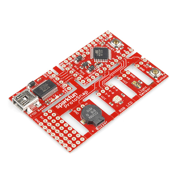
Due to our shipping and panelization process, this type of board is not fully supported, but can be fabricated with careful consideration and experimentation.
Design Considerations
These designs are almost always unique, since the number of shapes, sizes, and orientation varies wildly. The design also may need adjusting based on the intended user, intended usage, and board shapes. As a result, a bit of experimentation is always going to be required. However, here’s a few design tips to get things going.
- Always ensure that after snapping, you can connect the boards together easily. A small header pinout near the tab works most of the time, but some designs might work best with a special connector.
- Tab width is critical. If the tab is too narrow, it will not hold the board together well. Too wide, and it becomes difficult to break apart. 3-5 trace/hole pairs works best.
- Hole size / pitch. The best tabs have between 20-30 mil of material between the holes. A hole size of 25 mil generates pretty good tabs.
- Design permitting, having multiple tabs with 2-3 holes is better than one huge tab with 6 or more connections.
- Adding traces on both top and bottom of a tab is likely to result in difficult snapping. Consider instead using more tabs, or adding instructions to score the traces.
- Tab and board placement: Remember that your users has to remove these! If the boards are badly positioned, the tabs aren’t “snapped” as much as they are “twisted”. This can result in unusual failures.
Designing for Failures
Since these typically are for kits, the most likely failure that will occur is a pulled up trace. This is when the trace on the two boards doesn’t break, and starts pulling up traces inside your layout. Not good. Fortunately, the design can account for this in several ways.
Any of these techniques will generate a “stress concentration point” for a pulled up trace. This will cause a the trace to tear in a well-defined place, ensuring that it won’t affect your board.
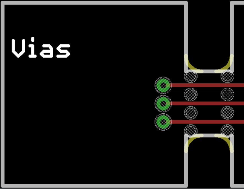
The simplest one simply having vias near the tab, as seen on the sparkfun board above. A ripped up trace will usually break at the edge of the via pad.
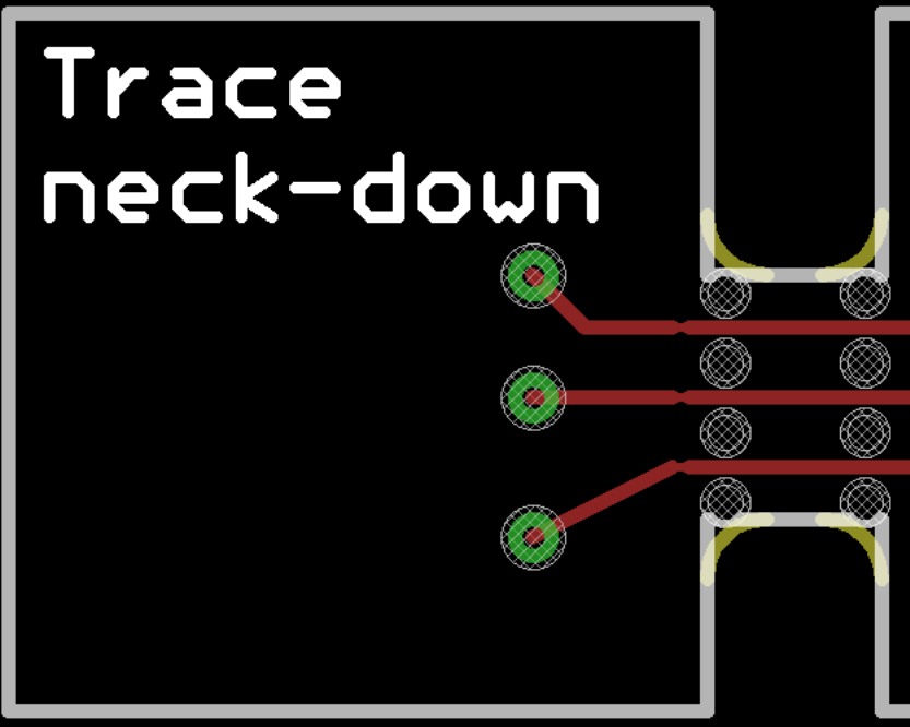
Another option is to actually narrow the trace near the board edge. This takes up less space than a via, but still provides a good weak point in a desirable location. However, make sure you don’t go too far below the design rules!
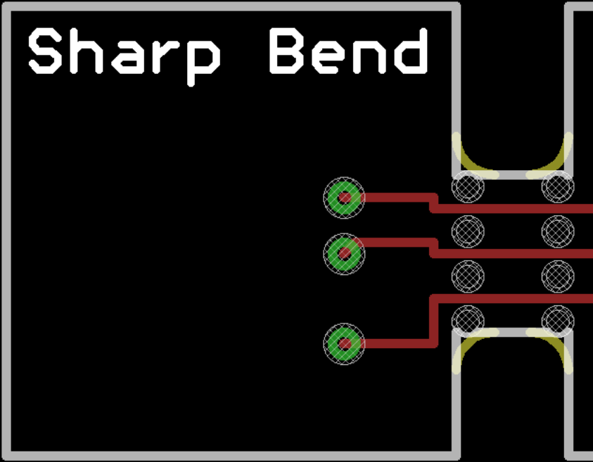
The last option is less ideal, but may suit certain layouts. Simply jog the trace, creating a 90* bend or two.
Indicating on the design
Here’s the measurements on our typical support tabs. Your design may require different configurations, so these are a rough guideline.
Typical tabs have the following features
- 20-25 mil drill hits
- 20-25 mil between the edge of the drilled holes
- roughly a 40 mil drill pitch
- 2-5 holes per tab (3-4 recommended)
- Holes tangent to the original board outlines
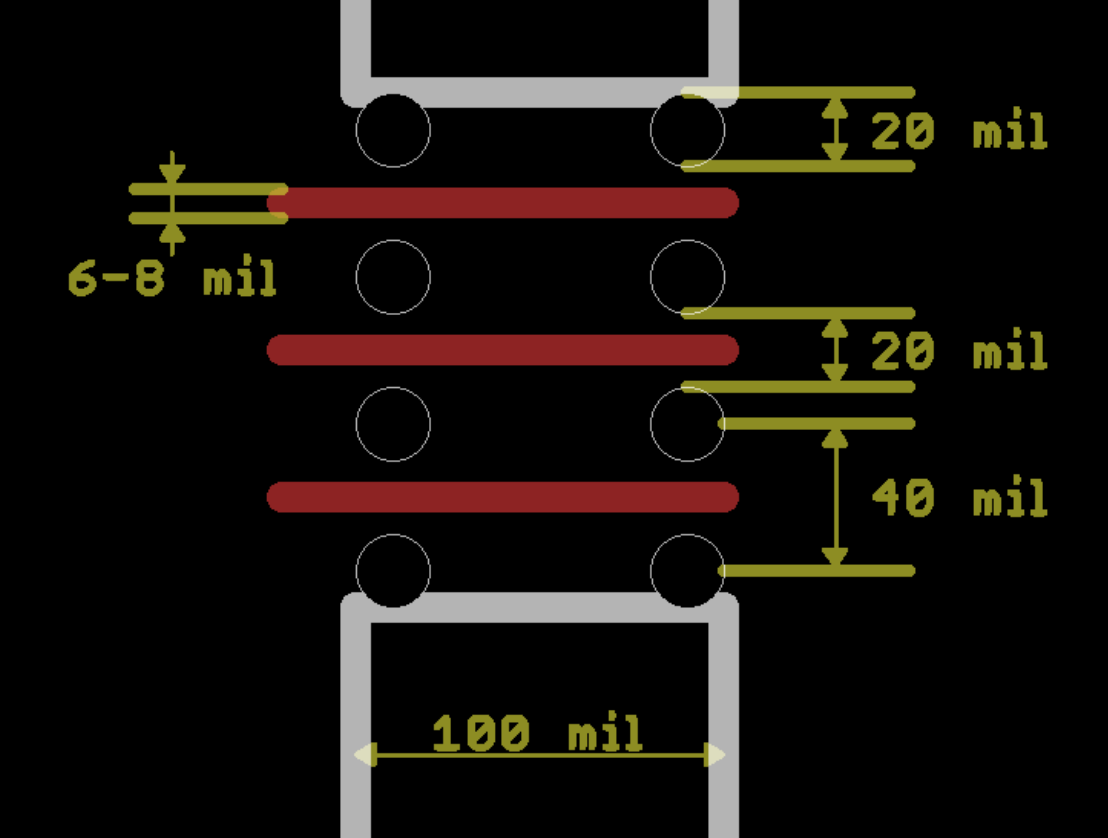
Note, the milling tool will add a 34 mil corner radius on the tabs. As a result, you can place the outermost holes tangent to the tab edge.
Failure modes (and how to cope)
Pulled up traces? Need to add a break closer to the edge, or score the board before snapping. Try to handle this on a design revision before a full kit.
