Generating Gerbers
Before you get started, you can upload .kicad_pcb files directly and we’ll generate the gerbers for you. For most users, this is the best way to order a board designed with KiCad.
Please email us at [email protected] if you’re having any trouble!
First Steps
Redraw Fill Zones
KiCad doesn’t automatically redraw the fill zones for certain changes, which can leave them out of sync with your other signals. This can result in the gerbers not matching the design, and ruining your circuit board.
To redraw these, simply use the hotkey b. Kicad will also refresh the fill zones when you run a DRC Check (under Tools > DRC).
Board Outline
We look for the board outline on the Edge Cuts layer to tell the fab where to cut the board. You can also indicate cutouts on this layer.
Generate Gerbers
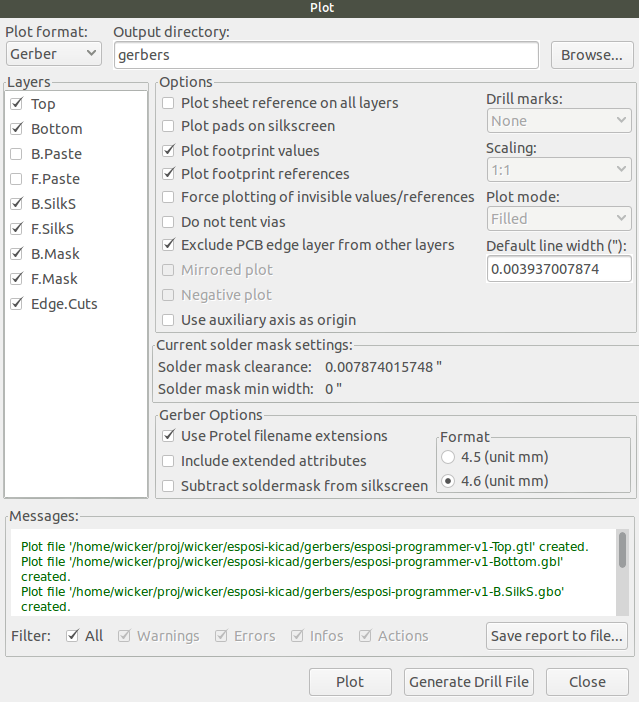
Select Files -> Plot from the menu to open the gerber generation tool.
It’s suggested to set the Output directory: to plots or gerbers. This will help keep the gerbers separate from the design files.
The Layers list will show the visible layers from the design. These layers should all be checked.
F.SilksF.MaskF.CuB.CuB.MaskB.SilksEdge.Cutswhich contains the board outline.In1.CuandIn2.Cuare also needed for 4 layer designs.
For the users options, we suggest the following. The other options can be set to your preferences.
- Uncheck
Plot sheet reference on all layers. This causes us to be unable to correctly determine board size, and makes uploads likely to fail. - Check
Exclude PCB Edge from other layers. This ensures that theEdge.Cutslayer doesn’t inadvertently cause shorts to features near the edge.
We suggest checking the Use Protel filename extensions, but it’s not required. Our system will detect all Kicad filenames.
Clicking Plot will show output in green and create gerber files in the output directory.
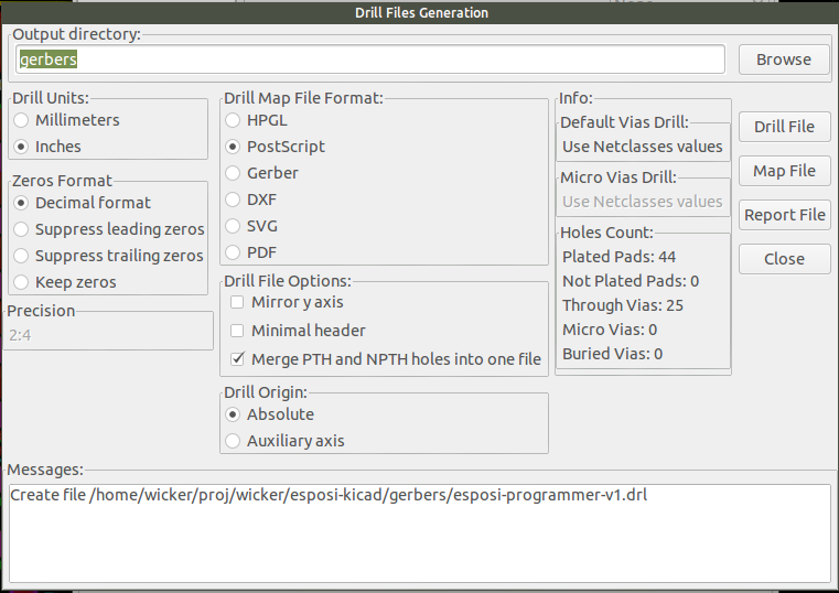
Drill Files Generation
Next, click Generate Drill File. The default options will typically work perfectly.
The only important options are
- Check
Decimal Format - Uncheck
Mirror Y Axis - Checking
Merge PTH and NPTH Holes into one fileis suggested, but not required.
Click Drill File and you should see a message in the bottom text window indicating that new files were created
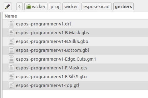
Verify the Files
Next, click Close to exit the Drill and Plot windows. All of the files should have appeared in your gerbers folder.
Before uploading your files, you may wish to verify the gerbers on your system. We suggest using Gerbv, a have a guide for Verifying your gerbers. Kicad also comes with a tool called GerbView that can be helpful.
If everything looks OK, select all of the files, zip them up, and upload the zip file to oshpark.com.