Submitting Panels and Panelized Designs
We support panelized designs, provided they meet our guidelines below. However, care should be taken to ensure successful fabrication, so careful reading of this document is encouraged.
Typically, panelized designs are used to reduce part count for pick and place assembly, or for simplicity in providing multi-board kits such as SparkFun’s ProtoSnap kits. It can also be used to utilize otherwise lost space in large, oddly shaped designs.
Submission Requirements
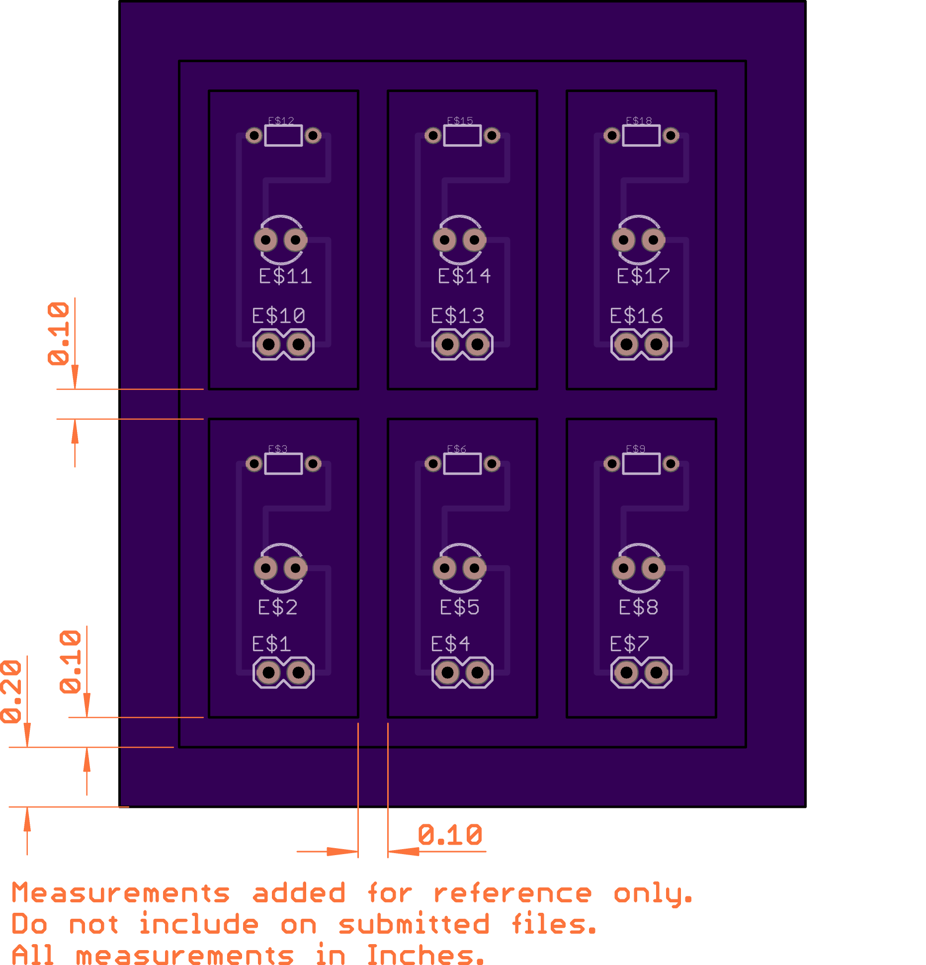
- Must provide 0.1 inches between the outlines for each panelized board
- A frame is required for us to guarantee the safe arrival of an intact panel. The frame must be at least 0.2 inches thick.
- Support tabs are not required, but can be added if desired.
- Our manufacturing quantity restrictions apply to panels, so our process would produce 3 copies of your panel. For a Medium Run order, we would instead produce 10 copies of your panel. It’s not possible for us to produce a single copy of a panel.
- Support tabs are optional, and will be added automatically during our fabrication process.
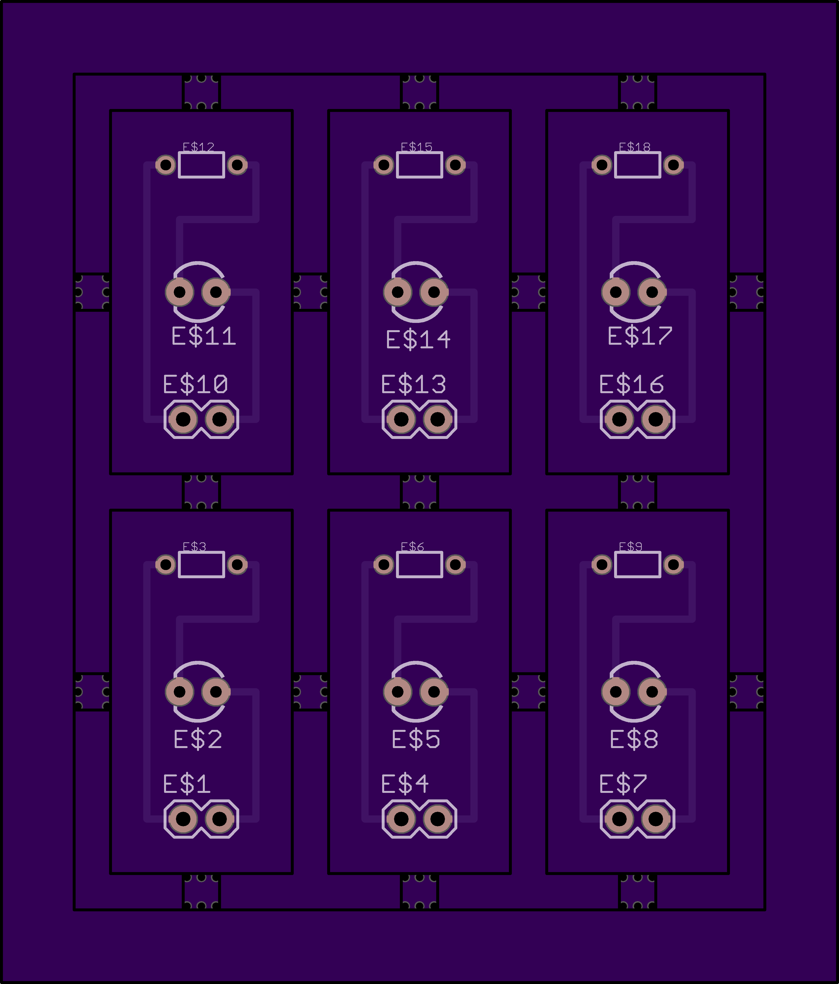
This image shows the dimensions required. The frame should not contain any measurements or fabrication notes, as they can cause complications during fabrication.
The panel may contain any number of boards. However, it’s helpful to consider the number of panels you will be recieving when setting up your panel.
Rendering notes
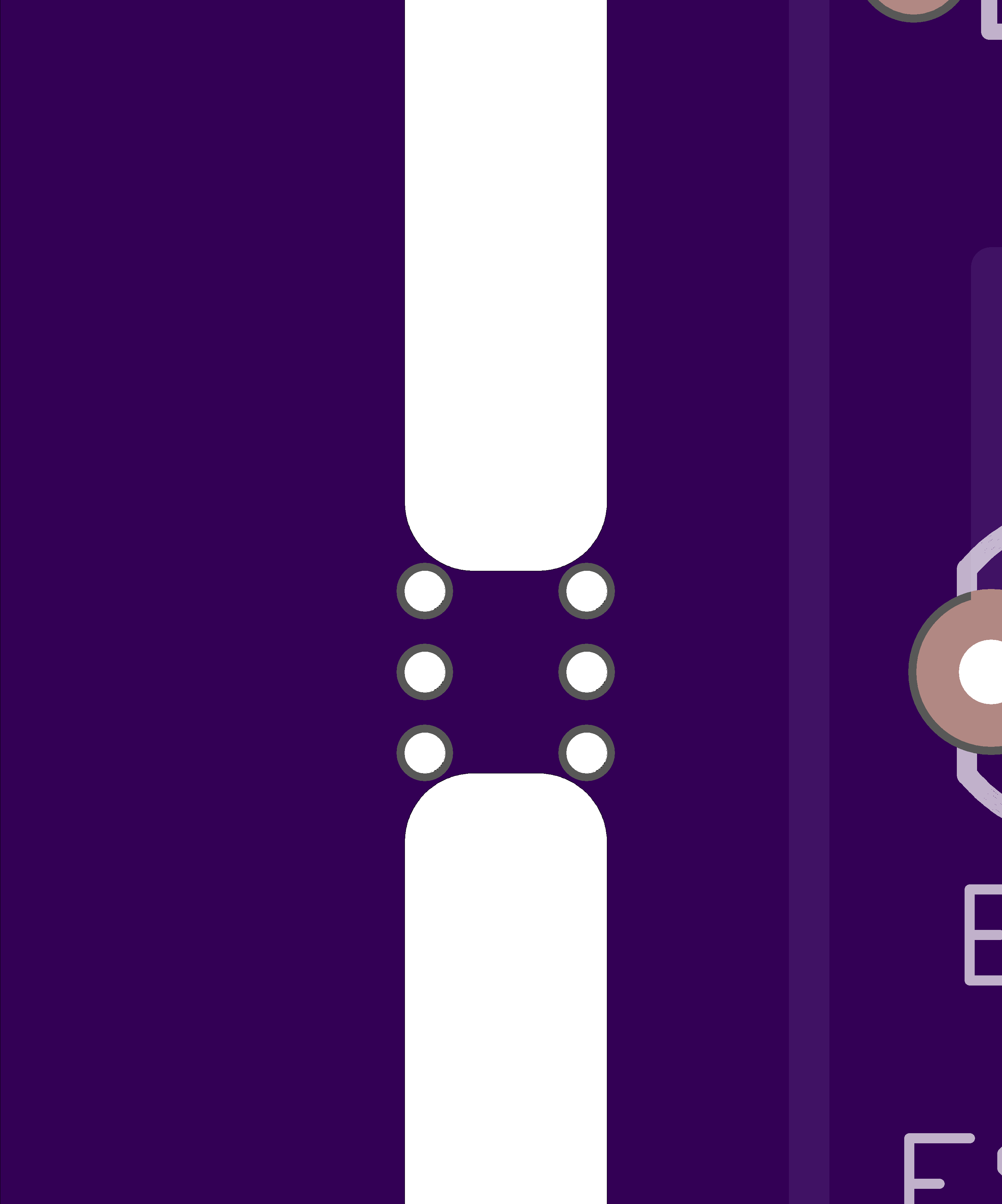
Our web rendering does not accurately show the internal cutouts of panels. As a result, a rendered panel will typically look like the image below.
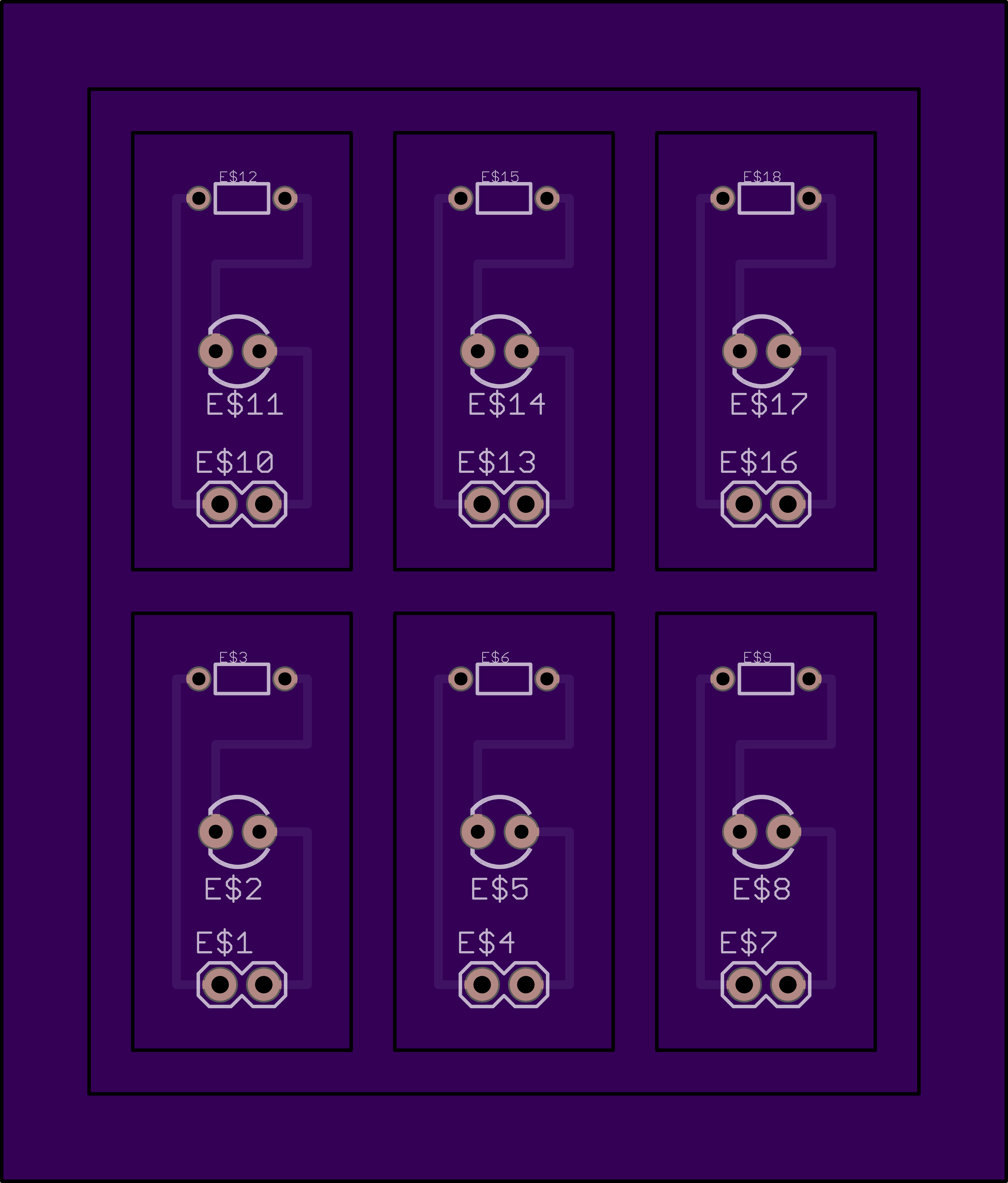
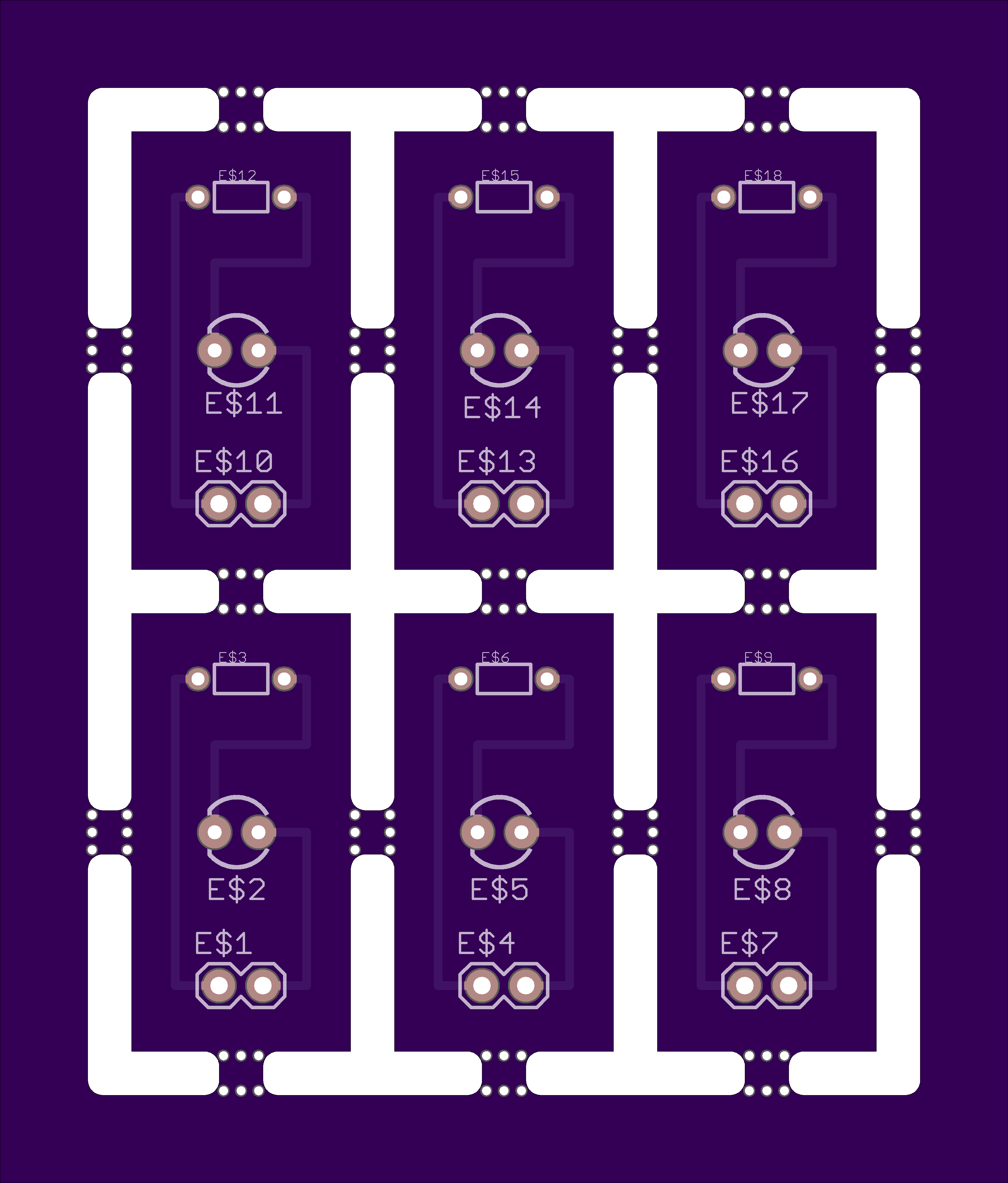
This is expected, and will be fabricated correctly. After fabrication and our automatic tab placement, the board sent to you will closely resemble this image
Note, large panels (typically over 80 square inches) may not process correctly when using our automated upload. For panels of that size, please contact [email protected] for assistance in placing the order.
Considerations for Pick and Place Assembly houses
If you’re considering getting your boards professionally assembled, we highly encourage you to talk to your assembler before laying out your panel. They may have important notes that add further constraints on panel layout. Among the more common considerations and surprises we see:
- Assemblers may have additional requirements for a frame or mounting fixture.
- Most assemblers require fiducials, either on each board or on the frame of a panel.
- Assemblers typically need panelized stencil gerbers, although often the top soldermask layer will suffice.
- Assemblers often charge per-panel handled. In some cases, it’s less expensive overall to order 3 large panels through our prototype service than 10 smaller panels through our medium run.
- Assemblers may not want multiple unique on each panel, due to part counts and feeders available on their machines.
- Make sure your panel doesn’t exceed your assembler’s work area. Most pick and place machines have a smaller maximum size than PCB manufacturers do. A common maximum work area is 9”x13”.
Adding tabs manually
While optional, certain panels or designs may work better when tabs are added by the designer.
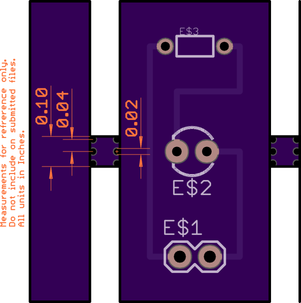
When manually adding tabs, we suggest the following measurements.
Note, that our automated rendering will not show the internal cutouts, so a render with tabs will look similar to the following.
Adusting tab strength
You can reduce tab strength by increasing the hole size to 0.025”, while keeping this pattern. Tab strength can be adjusted by slightly the spacing between holes between 0.035” and 0.045”.
Note about tabs and milling
Due to the radius of the mill end use fabricate the boards, the tabs will have a small corner radius, and not be perfectly square. Typically, the corner radius is 0.034”, corresponding to a 0.068” mill end. In some cases, our fabrication process may result in a 0.050” radius if a 0.100” mill end is used.
It is not required to account for the milling tool or interior corners on your design, and using simple lines to indicate your tabs is reccomended.
