Create a Board Outline
So you’ve got a set of generated gerbers where the files match our suggested naming pattern but there’s no board outline on its own layer. Here’s how to create one.
First, open all the layers in GerbV.
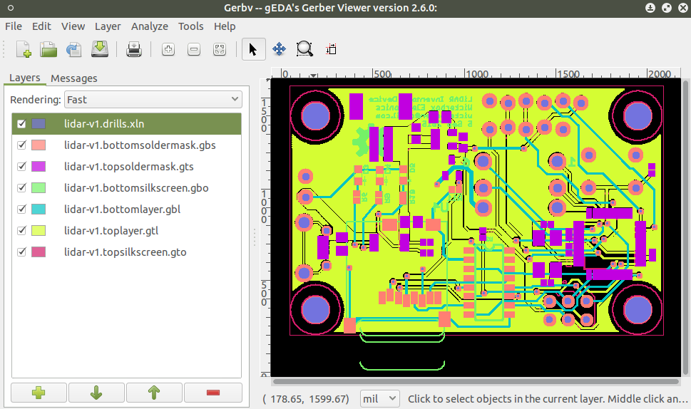
Next, identify which layer the board outline is on.
If the outline doesn’t appear on any of the layers, the first thing is to check the Design Tools help pages to see if we have instructions for creating one for your CAD package. If that fails, send over your design files to [email protected] and we’ll make one for you.
In this case, the board outline is on the Top Silkscreen layer (in pink).
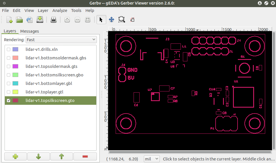
Now, you can save the Top Silk layer with a new name by going to File > Save Active Layer As. It doesn’t matter what you call the new file, just so long as it ends in .gko.
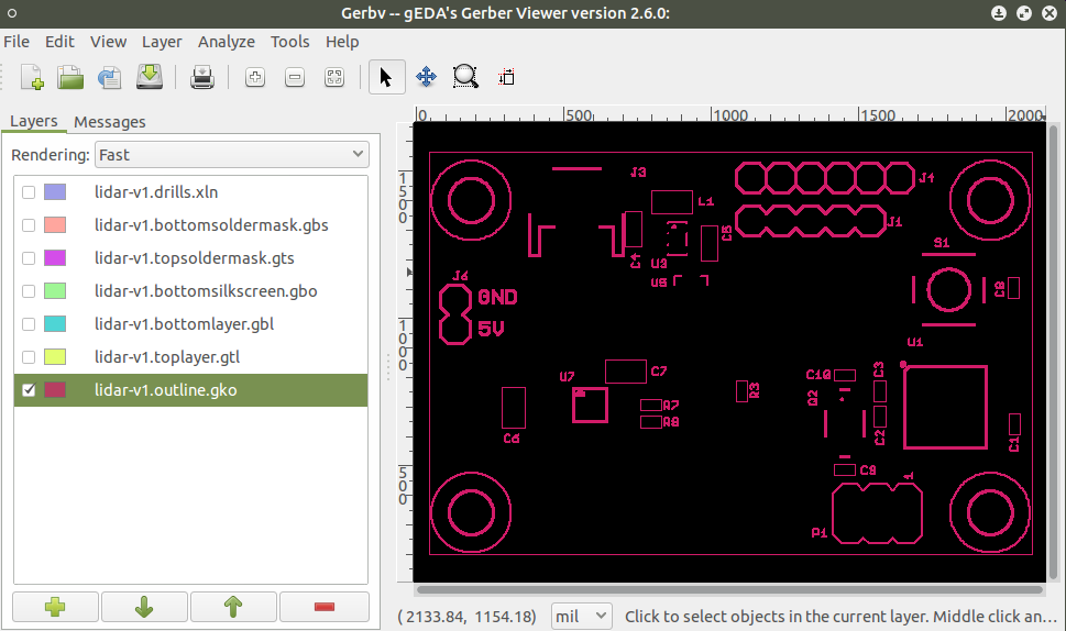
When you save, you’re making a copy of the layer and it will show up as a replacement for the Top Silk in GerbV’s layer menu. I like to immediately go and add the Top Silk layer back into the list so I have it to compare.
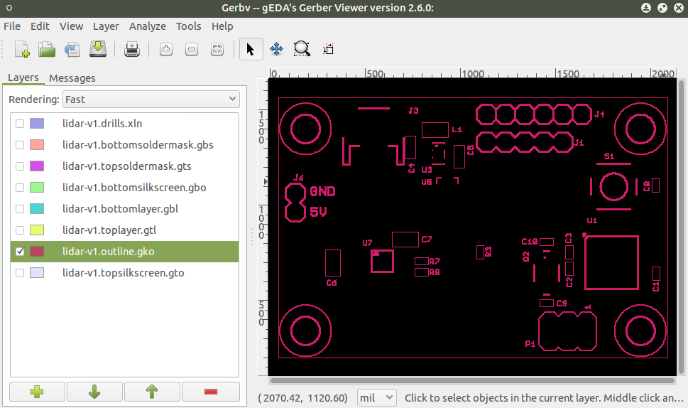
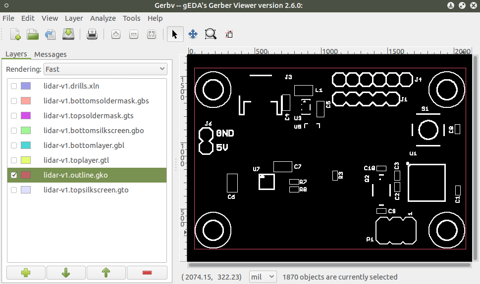
Make sure that your outline file is highlighted (active) in the left-hand GerbV viewer. Now you can click and drag to highlight all of the elements you want to delete off this layer. You can click, click and drag, and hold down shift to select multiple items at once. When everything except the outline itself is highlighted, it should look like this.
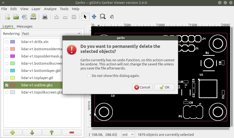
Hit the delete key and you may get a dialog box.
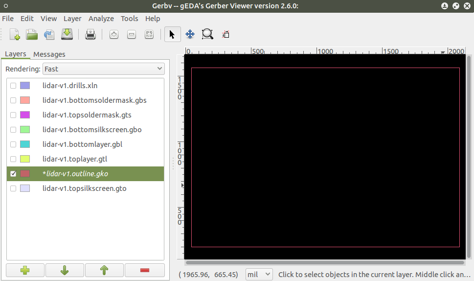
Hit OK and now you have a beautiful board outline on the correct layer by itself, with no extra text or anything. You’ll notice that the text on the left is in italics. Go ahead and hit Ctrl+S to save the layer, and it will go back to normal text.
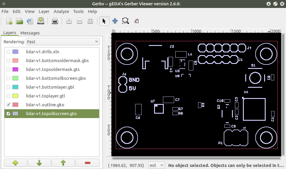
The last thing I always do is turn on the silk layer to compare. If this was the copper layer, I usually delete the board outline on the copper layer so the fab doesn’t accidentaly place copper around the edges of my board. It’s totally up to you.
Zip up the gerber files and the site should accept them without any outline-related errors.
