Allegro / OrCAD
Cadence Allegro and OrCAD are professional, downloadable PCB design tools that are closely related and that run on Microsoft Windows.
Design Rules and Technology Files
OrCad stores the design rules in Parameter and Technology Files. We don’t provide these files directly, so you’ll want to refer to our Services pages to find the design rules of the service you want.
Once you know the rules, we recommend this tutorial for getting started with setting up your own files.
Generating Gerbers and Drills
We expect to receive a zip file containing individual gerber layers in RS-274X (Extended Gerber) format along with an NC drills file exported with 2:4 inches or 3:3 metric precision, absolute coordinates, and no zero suppression.
To get all the files, there are four screens. First, go to Export -> Gerber Parameters and set them like this:
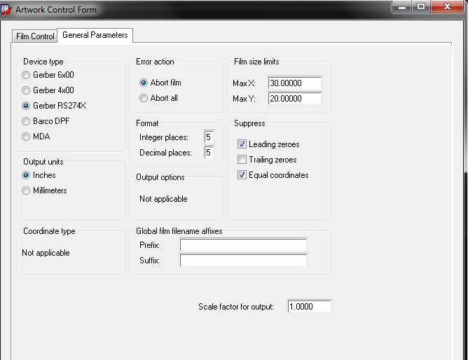
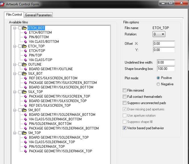
Then, Export -> Gerbers (Film Control) and set them like this, then Create Artwork.
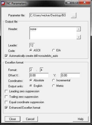
Access the drills menu with Export -> NC Drill Parameters and set them like this:
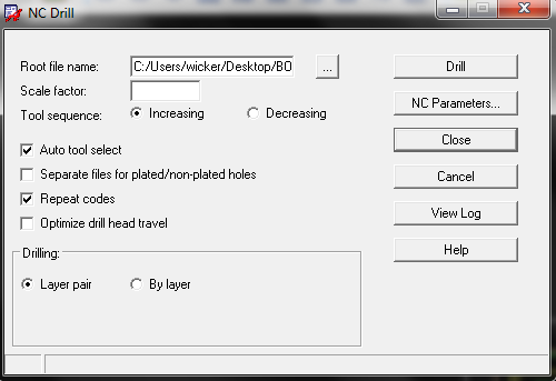
Then, Export -> NC Drill and click Drill to generate the drill file.
Cadence Allegro Drill Settings
In Cadence Allegro, these two settings are disabled by default but need to be enabled:
- Check
Enhanced Excellon Format - Check
Auto Tool Select
It should also be in 2.4 precision with no zero suppression.
Our Drills article has an example of how an image preview should look for the drill holes to be placed and drilled correctly.
Renaming Gerbers
ORCAD usually produces all gerbers with a .PHO or .ART extension. Our site may not always parse this correctly. If your files are not detected, or detected incorrectly, try renaming them to our suggested naming pattern
Often, ORCAD produces several different drill files,
Correct Drill Files
thruhole.tap: This is a correctly formatted NC Drill file. We’ll detect this if provided.filename.drl: This will be detected. If the file contains format issues, it will generate warnings by the site. See the drill format section for how to resolve these as necessary.
Incorrect Drill files
ident drawing.artor “drill drawing”: Contains human-readable drill information, but cannot be machine processed.- Drill Guides: Contains human-readable drill information, but cannot be machine processed.
filename.dts: Contains number of drill hits, but not drill coordinatesnc_param.txt: Contains drill metadata, but not drill coordinates
Missing Board Outline
Make sure it’s a watertight outline on a layer by itself.
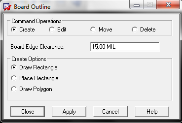
There is a potential issue with outlines that will cause our site to return an internal error or be otherwise unable to find the board outline. This happens when a particular layer is set so that zero width lines get plotted as zero width. This means the Gerbers don’t contain the line, so we can’t see it.
To fix this, change the line width from 0 to 1 mil for ‘undefined line width’ lines on the layer with your board outline.
Note for ORCAD UNISON users
Ensure that the option Keep Drill holes Open is unchecked. You’ll find this option under the Post Processing Settings. Checking this option will cause misinterpretation of drill holes, and will result in vias being unplated.
