Cutouts and Slots In Eagle
Board Cutouts
Board cutouts are commonly used to indicate a non-plated region of the board that can be removed. See Board Outlines for additional details on this style of cutout.
For Eagle, these should be drawn on the Dimension layer using the Wire or Line tool. Simply draw the edge of the area that you want removed. Board cutouts have a minimum width of a 68mil (1.7272mm), which is the size of the tool used to fabricate them.
Cutouts that are drawn over copper features (traces, holes, etc) are not supported, but may work.
Slots
Important Notes about designing Slots in Eagle
Eagle does not have internal support for slots. This has several consequences for designers:
- Eagle’s DRC checker have several situations where slots are not checked.
- Eagle can not export a “drill slot” file directly.
- Lots of inconsistency in how slots are indicated with existing designs and footprints
- Fabs may have special requirements for how to export slots
As a result of this, getting guaranteed slots requires special attention to avoid design or fabrication issues.
Important Notes about ordering Eagle slots
We have full support for NC Drill files that include slot data. However, Eagle has no way to produce slot data in NC Drill files. As a result, designers wanting guaranteed slots can do the following to opt-in to an automated workaround in our process:
- Drawing the slot as described below using the
Millinglayer. - Verifying certain DRC aspects which Eagle does not account for.
- Ensuring that the
Millinglayer does NOT contain legacy slot drawings or non-slot data - Ordering using gerber files generated using our Slot Path CAM job below
- Ensuring that our site generates a
Detected Supported Slotsnote on the upload.
These requirements are to avoid various issues with Eagle’s DRC, conflicts with existing designs using the Milling in unexpected ways, and our own file cleanup of drill files.
OSHPark Eagle tools
Our OSHPark Eagle Tools Eagle script will install the appropriate CAM jobs, as well as help update them if anything changes.
If you already installed this, you can simply Update and the script will add the new CAM jobs.
This repository also has additional 6 layer CAM jobs, DRU files, and other helpful files for Eagle.
Eagle 9.2 and newer
Eagle 7.2 to Eagle 8.6
Eagle 7.1 and older
⚠️ Verify All Internal layers!
When using Slots with a 4 or 6 layer PCBs, you MUST manually verify internal layers. Eagle’s DRC does not respect any method of making slots, and copper pours or auto-routed traces will short to the slot.
To resolve these issues, you’ll need to use Wires to replicate the copper being added to the Top and Bottom layers for your slot.
Standard Slot Restrictions Apply
In addition to Eagle quirks and restrictions, slots must comply with standard support requirements as noted here: Slot Support
Drawing Eagle Slots
Plated Slots
At minimum, a slot requires the following:
- Copper beneath the entire slot
- A valid annular ring on all parts of the slot
- A line representing the slot path and slot width on the Milling layer.
The easiest way to draw slots in Eagle without unexpected issues is to do the following:
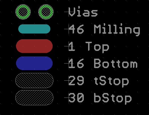
- Add 2 Vias, representing the start and end of the slot. Set the Drill property set to the desired slot width.
- On the Milling layer, draw a line between the center of each via. Set the Width of this line equal to the slot width.
- On both Top and Bottom layers, draw a Wire between the center of each via. The Width of this line typically would match your Pad size, but at minimum must be
(slot width) + 2*(annular ring) - For 4 layer boards, draw 2 additional Wires on the internal layers to connect traces. It’s recommended to ensure the Net is correct.
- On the tStop and bStop, draw 2 more lines between the via centers. The Width of these lines should be the same as the copper. Optionally, you can make them up to 4mil (0.1016mm) wider to account for mask expansion.
- Export the gerbers using our CAM job with slot support.
The end result is 5 lines which all have the same start coordinate, same end coordinate, and a via on both start and end coordinates.

Plated Slots in Footprints
Plated slots can also be created using a Long Pad inside component footprints. This is similar to the above, except that the Pad object automatically generates the required copper, tStop, and bStop layers.


Notes about this approach:
- Long Pads can only be created as parts of component footprints. For slots not in a footprint, use our other recommended method.
- The properties of copper on Long Pads is dependent on the DRC settings in the Shapes tab. Unexpected changes in this tab can potentially result in slots being fabbed in unexpected ways.
Non-Plated Slots
Non-plated slots have the following requirements:
- Must NOT have copper below the slot
- A line representing the slot path and slot width on the Milling layer.
The easy way to represent this in Eagle without issues is as follows:
- Either load our DRC file, or verify that the DRC setting
Distance > Copper/Dimensionis greater than zero. We recommend 15 mil (0.381mm) for our service. If this setting is zero, Eagle will not remove copper from beneath the cutout, which will result in the slot being plated. - Draw a line on the Dimension layer, with the start and end coordinates representing the start and end of the slot. Set the Width equal to the slot width.
- Draw an identical line on the Milling layer. It should have identical start and end coordinates, and the same Width.
- Export the gerbers using our CAM job with slot support.
The two different layers have different purposes:
- Milling is used to indicate the slots during CAM export and our processing. However, it does NOT interact with Eagle’s DRC.
- Dimension is used to apply DRC rules to the slot. This is most notable on copper pours near the slot.
- Dimension also serves to provide legacy data for other fabs and CAM jobs.


Alternative Non-Plated Slots
Some users or designs may wish to continue using the “cutout” or “boundary” style Dimension layer, but also want fully supported slots. This is not an issue.
To do this, simply
- Draw the slot boundary on Dimension. The center of this line should represent the board edge. The line width should generally be 1mil (0.0254mm) to 10 mil (0.254mm).
- Draw a line on the Milling layer, with the start and end coordinates representing the start and end of the slot. Set the Width equal to the slot width.
- Either load our DRC file, or verify that the DRC setting
Distance > Copper/Dimensionis greater than zero. We recommend 15 mil (0.381mm) for our service. If this setting is zero, Eagle will not remove copper from beneath the cutout, which will result in the slot being plated. - Export the gerbers using our CAM job with slot support.
Notes about this approach:
- In case the Milling and Dimension layers are misaligned or mismatched, we make no guarantees about which layer is treated as “correct”.
- The Width of the Dimension lines alter how Eagle applies the Edge Keepout spec. This is most notable near copper pours. Eg, a 10mil dimension line removes more copper than a 1mil line does.


FAQ
Do I need to adjust my existing designs?
Nope! Read the next question for details.
Can I just upload my old stuff as always?
Yep! Legacy slot support remains unchanged. This means that (most) slots are unsupported but will usually work.
The only previously supported slot type is non-plated cutouts at least 68mil wide, and indicated as a “board cutout” or as a slot path on Dimension. This will continue to be fully supported.
If you need the old documentation for some reason, it’s now located here: Legacy Slots
Do I need to use the new CAM?
Yes. This is to ensure that the designer has verified the correctness of their design, and that their Milling layer properly represents slots as we expect them.
We feel this is important since Eagle itself does not have a proper process for slots. Trying to make slots in Eagle means granting electrical connectivity to a non-DRC verified layer (Milling). This can result in uncaught errors, which can destroy a board, and potentially any equipment plugged into it.
What happens if I upload a .BRD file or use a different CAM job?
Your slot will be treated as all legacy slots are. This means your slots will not be guaranteed, but will usually work.
Our legacy CAM jobs and BRD upload use both Milling and Dimension for the outline layer. This means
The instructions we provide will generate a “slot path” on the board outline when used with other CAM jobs or when a .BRD file is uploaded.
Can I use these instructions to get slots from other fabs?
Probably! We’re not doing anything radical: the Dimension and Milling layers have been used this way for years.
We’re just offering support to one of the many ways these layers are used, with the hope that it makes things simpler, more consistent, and more robust.
Why don’t you just make a new custom layer for slots?
We considered it, but it’s not a great idea.
Milling is historically used for milling/slot data, and this is known by most designers. This means anyone editing a design will look here for slot info.
However, it’s easy to miss custom layers, especially if a designer does not work with us regularly. This means someone editing a board may inadvertently adjust the board without adjusting the slot data. This would result in parts missing slots, or slots appearing where they shouldn’t.
A new layer would also remove all backward compatibility with other processes.
Do you have examples?
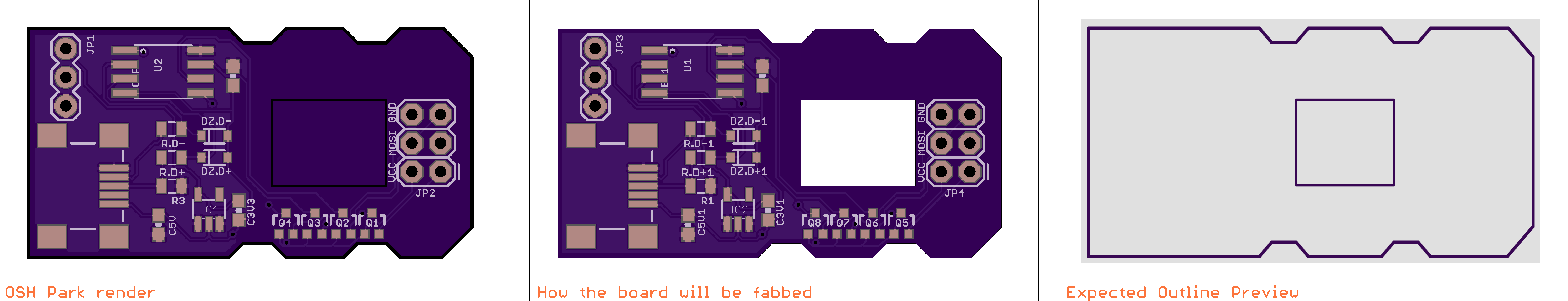
Yep! See this attachment, which provides a fairly comprehensive way of using slots and milling in Eagle.
What about drawing it like __ ?
We’d recommend the above approach instead. There’s lots of ways to draw things in Eagle, but most of them have issues or shortcomings that make them unreliable. Our slot reference includes several examples of slot styles we’ve seen, as well as some problems that turn up when using them.
I need to use drill slots with other software/fabs. How do I do that?
Easily! We planned for this.
- Use our CAM job
- Open the .slotdrills.xln file in Gerbv.
- Go to File > Export > Excellon Drill.
- Select the .slotdrills.xln file, and click OK.
- Close Gerbv, and re-open the .slotdrills.xln file to verify things
Done! You now have a true drill file with slots.
Note, however, that not all versions of GerbV support slots. If you re-open the converted file and there’s no slots, this is likely the case.
Can I avoid this by just using holes?
Certainly! In a lot of cases, you can just use holes instead of slots. Just make the diameter of your Hole or Via equal to or larger than the original length of the slot.
A lot of Eagle libraries include components that have already done this for you, so consider checking if this comes up.
