Board Outline
Our service requires a board outline gerber, which indicates to us and the fab where the edge of your board is to be located. This layer is used by our service to generate the billing cost based on your board area, as well as enabling us to remove data that lies outside your board to avoid affecting adjacent designs. The fab also uses this outline to determine how to cut your board out from the panel.
While most design tools make producing this layer fairly straightforward, some design tools include additional data that causes issues, or fail to generate it at all. If our system rejects your board due to outline or size issues, try going through our outline troubleshooting guide, or contacting our support staff at [email protected]
Limits
The smallest dimension of your board can’t be smaller than 0.25 inches. The smallest board you can make is 0.25 inches by 0.25 inches.
The largest dimension you can have is 16” by 22” inches.
Board Outline Preview Images
Fab interpretation
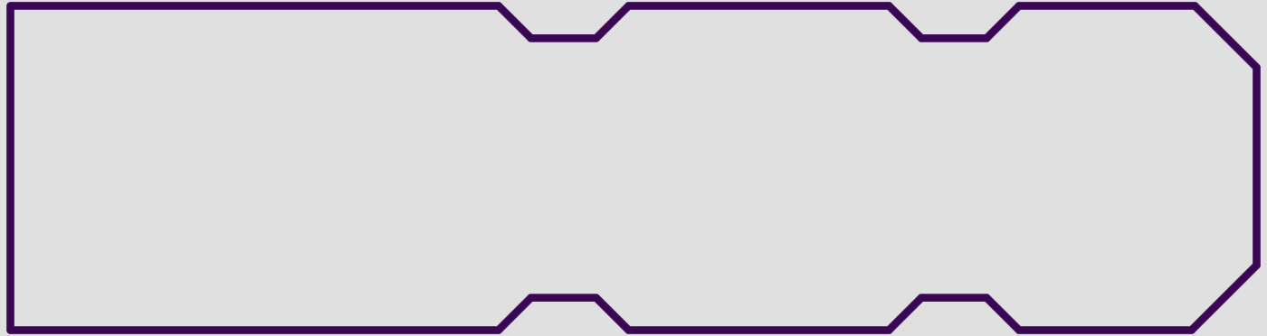
The following image indicates how the fab interprets the data from your board outline layer. We recommend a small but nonzero line width; the fab will route so the edge of your board is at the center of your line, no matter how wide it is.
Board Slots
Whenever possible, we recommend using your design tool’s drill slot tool to create slots. See more at our Slots guide. This will allow for fully supported slots.
Design tools that do not have a drill slot command (notably Eagle), the outline layer may contain data for slots. Slots drawn this way are not fully supported, but are typically fabbed without issue.
Board Cutouts
Board cutouts are indicated identically to the board outline, but represent a region of the board to be removed instead of the outer edge. All board cutouts are non-plated.
We can guarantee correct fabrication of board cutouts that meet the following design criteria:
- Cutout dimensions exceed 0.068” x 0.068” (1.7272mm).
- Can be any shape that can fit a 0.068” (1.7272mm) mill end.
- No copper present beneath the cutout.
- The cutout does not intersect with the board outline. Notches on the board edge are permitted, but should be drawn as part of the outline.
The following callout criteria is also required:
- The cutout is drawn using lines forming a closed shape. Polygons, flashes, or other filled shapes are not guaranteed to work correctly.
- The line width used for the cutout will be ignored, and treated as if it has a width of 0”.
- The board outline layer contains only details pertaining to the board outline, cutouts, or slots. Drill drawings, PNP data, or annotations can cause slots to be disregarded. As an exception, complex or nested cutouts may contain the text
CUT OUTplaced inside the cutout, but this is not required.
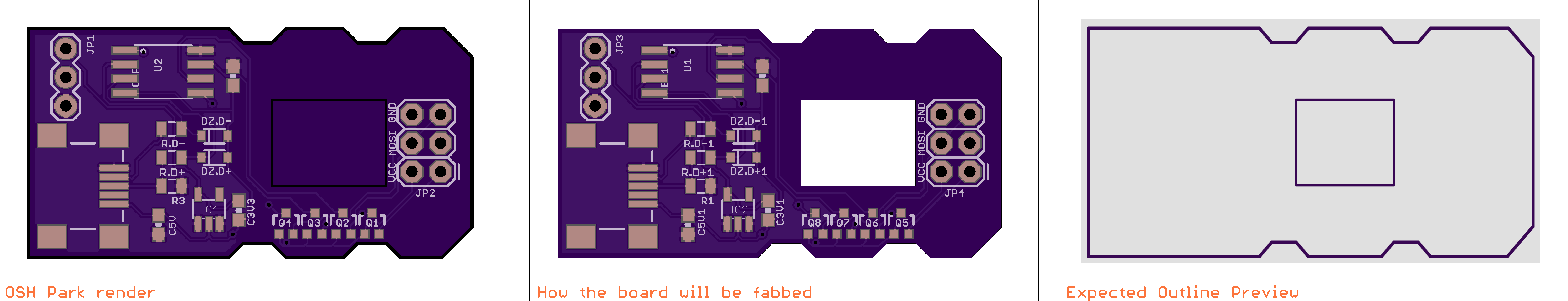
Note, currently renders for the board will not fully handle board cutouts. Paying close attention the the thin black lines of the Top preview, as well as the board outline will ensure that your cutout is detected for fabrication.
When making a circular cutout under 250mil, we recommend simply using a non-plated hole.
Milling Size
Typically, board edges and cutouts are cut with a 0.068” (1.7272mm) milling bit, for a 0.034” (0.8636mm) interior corner radius.
Smaller bits down to 0.04” (1.016mm), with a corner radius of 0.02” (0.508mm) may be used when needed for an outline or cutout feauture, but their use is not guaranteed.
Calculating PCB Size
The size of a PCB is determined by the smallest rectangle that will enclose the design. Arbitrary board shapes are allowed, but will be billed as if they were a rectangle, as shown below.
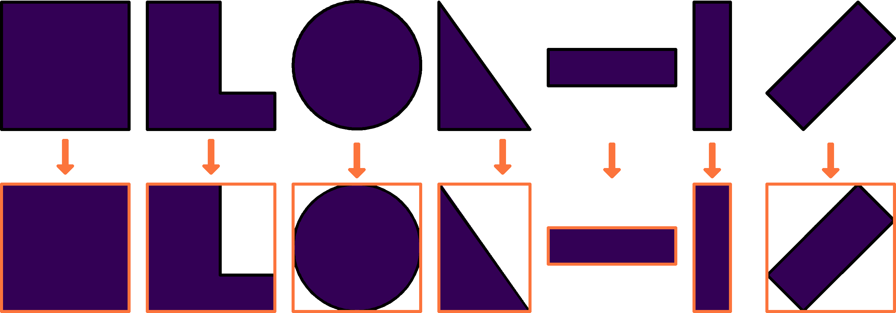
PCB areas are rounded to the nearest thousandth of an inch.
If a board size or shape seem incorrect, see the outline issues page for more information.
