Common Errors with Drill Files
Almost all drill file issues are the result of incorrect output formatting. When in doubt, check our Design Tool Help page for your tool to correct any errors.
If your tool is not listed, or you just want the expected format values, see our Drill Specs page
Why is my drill file “blank”?
This may be due to a number of reasons, often specific to the tool you’re using.
For single-sided SMD boards, this is because there’s no drill hits within the file. This is perfectly acceptable, as these boards may not have drill hits.
ORCAD’s default configurations often does not generate a standards complaint drill. Our help page covers the options needed to correct this.
Altium sometimes generates a binary drill file, which we interpret as blank. However, since Altium also generates a .TXT file which we can read, this is rarely a problem.
Older tools sometimes generate the drill data in two files: A “Tool” file with a TOL file extension, and a “coordinate list” file with theLST extension or an incomplete NC Drill file. Our Manually Adding a Tool List guide will help convert these two files into a single drill file we can understand.
Why is it saying my drill file is missing?
Quite commonly, this message appears because the drill file was blank, and then removed.
In most other cases, this means that the file is not in the zips you uploaded. Many tools generate Drill Files in a different step than the Gerber files, making it easy to forget.
In rare cases, the drill file may have a file name we don’t understand. Make sure your files match our Suggested Naming Pattern and try again.
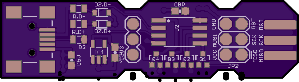
Why is everything bunched up?
The exact position of the “bunched” drills may change depending on the design tool and the design itself.
This is sometimes caused by a drill file using Trailing Zero Suppression. Changing the Zero Suppression setting to None or Leading will correct this.
Occasionally, this error is caused by exporting with Metric units without a provided format specifier. In these cases, we suggest exporting the file with using Inches and 2:4 precision.
If you do not have the design files, you can use Gerbv to modify the drill format
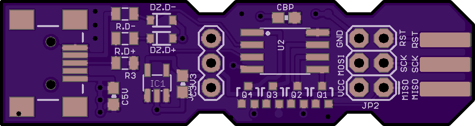
Why are only some drills bunched up?
This can be caused by a drill file using Trailing Suppression being set to Trailing.
Changing the Zero Suppression setting to None or Leading will correct this.
If you do not have the design files, you can use Gerbv to modify the drill format
Why are some holes missing?
 This is usually due to
 Trailing Suppression being set to Trailing. It’s possible for the zero suppression to only affect a small number of drill coordinates. When this happens, it often looks like holes are “missing”, since it’s hard to see where they wind up being relocated.
Changing the Zero Suppression setting to None or Leading will correct this.
Rarely, this is due to a zip file having multiple drill files, some of which are not detected correctly. In most such cases, this is due to the design having blind/buried vias, which we cannot fabricate.
Why are my slots missing?
This is likely due to the slot method used by the design tool not being supported. See our Slots page for more details.
Why are my drills are offset from my board?
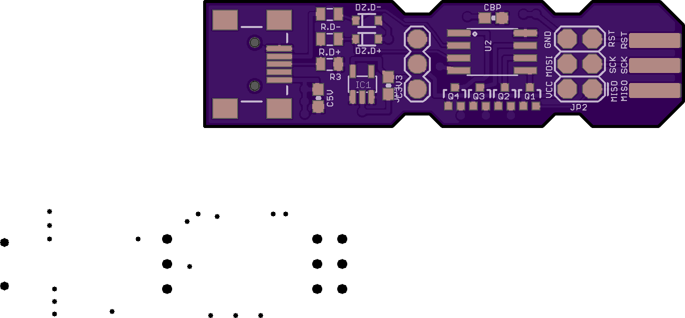
If the drills are bunched up, check the Zero Suppression and ensure the output unts are Inches, and the format is 2:4. See above for more details.
If the drill file looks “correct”, but offset from the other layers, then this is likely caused by having an incorrect Coordinate Origin setting. Since this setting only two options (Absolute and Relative), simply toggle this setting and create new gerbers. That should correct the issue.
If you’re using PADS, this may be more more difficult to resolve. See our PADS Design Tool Help page for further assistance.
If you do not have the design files, you can use Gerbv to modify the drill format
