Generating Gerber Files
First Steps
Before you get started, you can upload Eagle .brd files directly and we’ll generate the gerbers for you. For most users, this is the best way to order a board designed with Eagle.
Sometimes though, you might want to customize the silkscreen, manually verify the gerber files, or other things that require manufacturing files. This guide will help with that.
We provide a standard CAM file that will automatically configure Eagle to a good starting point.
Validate Board Outline
One of the most common errors we see for Eagle is a missing Board Outline. Verifying your outline will save you a lot of trouble.
Eagle expects this to be drawn on the Dimension layer, using the Wire or Line tools. For many designs, it’s a simple rectangle or circle that contains your design. We’ll cut your PCB out using this layer as a guide.
Using our Eagle Installer/Updater
We have published some Eagle scripts to automatically download, install, Eagle files we provide. This is the recommended way to manage these files.
Downloading Manually
Select the correct CAM file for your version of Eagle, and how many layers you want to use.
For Eagle 9.2 and newer:
For Eagle 7.2 and newer:
For Eagle 7.1, Eagle 6, and Eagle 5:
A good place to save this is in your Eagle folder in the cam/ directory, since Eagle will assume your CAM files are in this folder.
Configuring CAM Output
Load CAM file
To load the downloaded CAM file, open your board layout window. Then, open the CAM processor by going to File > CAM Processor
In the new window, select File > Open Job, browse to the downloaded file, and select open.
Modify Layer Configuration (Optional)
Once the CAM file is loaded, you may optionally adjust the CAM files to suit your design. The most common adjustment is to add or remove layers that will be included on the silkscreen.
The tabs on top each represent a single Gerber file and a single layer on a fabricated PCB. The list on the right indicates the Eagle layers will be included in this file. It’s common for multiple Eagle layers to be used to generate a single Gerber file.
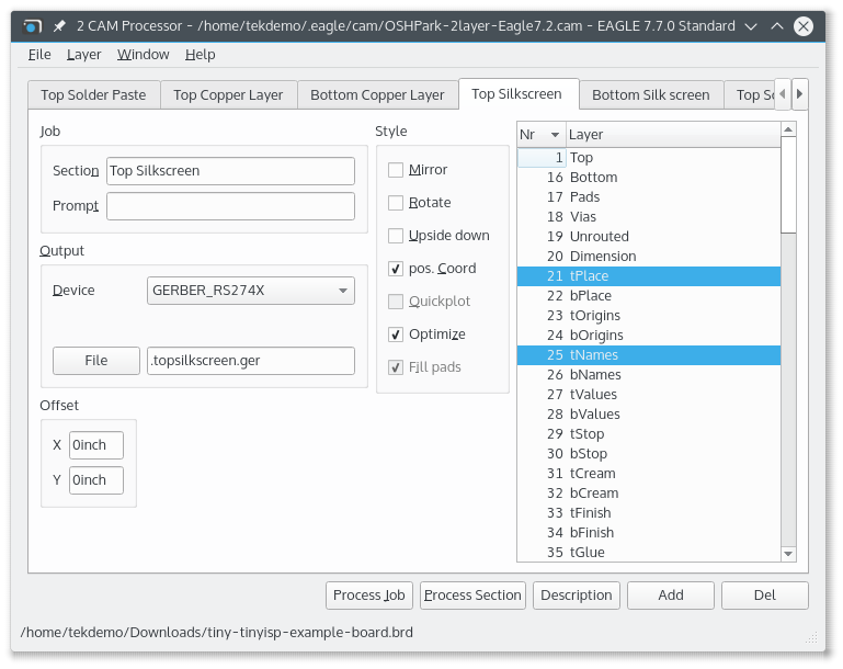
To adjust the layers used in each file, select the tab (such asTop Silkscreen), and check or uncheck any layers you would like printed. For a full list of layers and what they typically do, see our Eagle Layers Explained page.
As an example, you can include component values by selecting tValues, turn off component names by de-selecting tNames, or show all the Top traces on the top silkscreen by selecting Top.
Note, that while you can configure arbitrary Eagle layers to be included in arbitrary Gerber files, doing so impact the functionality of the board. Silkscreen files are purely cosmetic and safe to change, but excercise caution and verify your gerbers whenever you adjust any other gerber file layer configuration.
Generate the Files
Once the CAM file is loaded and configured to your liking, simply click Process Job. Eagle will then generate the .ger and .xln files in the same folder as your .brd file.
Eagle will also generate several .gpi and .dri files, which can be deleted or ignore.
From here simply zip the output files, and upload it to oshpark.com
