Cutouts and Slots In Eagle
IMPORTANT NOTE!
This page is for legacy tools only, and should be used only if your tool does not have a better way to create slot data.
For Eagle, see our Eagle Slots page. This includes more specific examples, and ways to get guarantees on slots.
For most other tools, check here: Slots
Board Cutouts
Non-plated board cutouts over 68mil (1.7272mm) are fully supported, and should be drawn on the tool’s Outline layer using the Wire tool. See Board Outlines for additional details and what to expect for these features.
Smaller cutouts and plated cutouts are not supported, but will work in many cases.
Cutouts that are drawn over copper features (traces, holes, etc) are not supported, but may work.
Slots
Officially Supported
We can guarantee correct fabrication of slots meeting all of the following criteria:
- No copper present below slot
- Have a width at least of 0.1” or larger
and drawn using one of the following supported callout methods
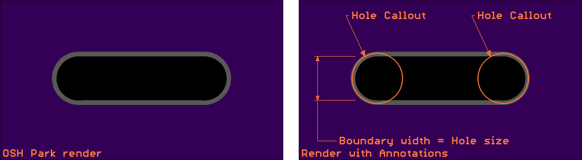
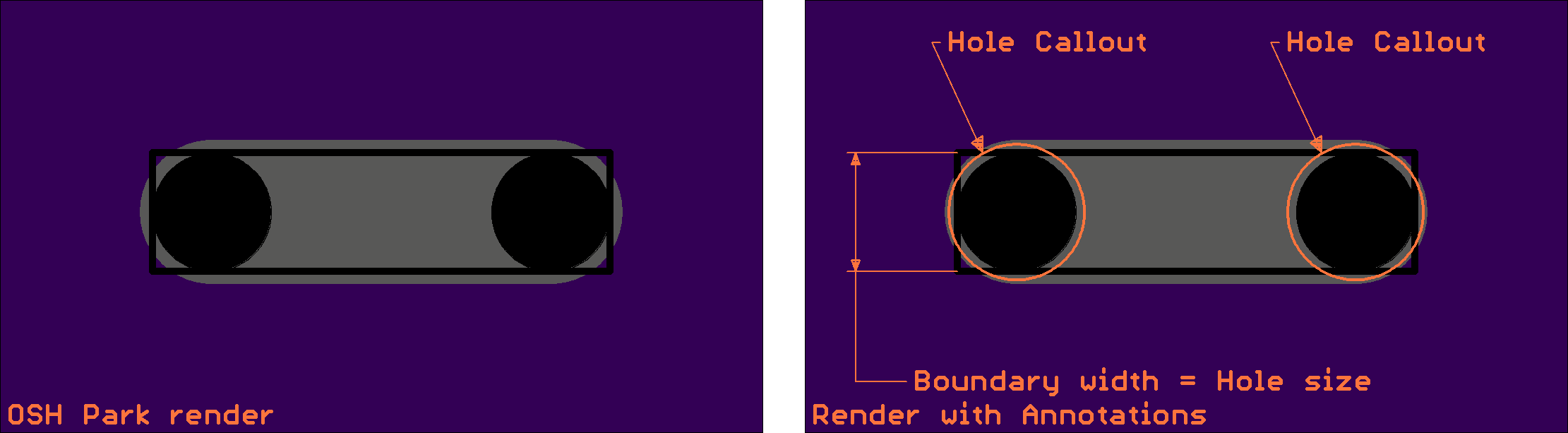
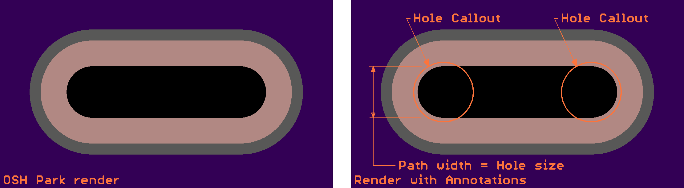
- Uses Slot Path callout
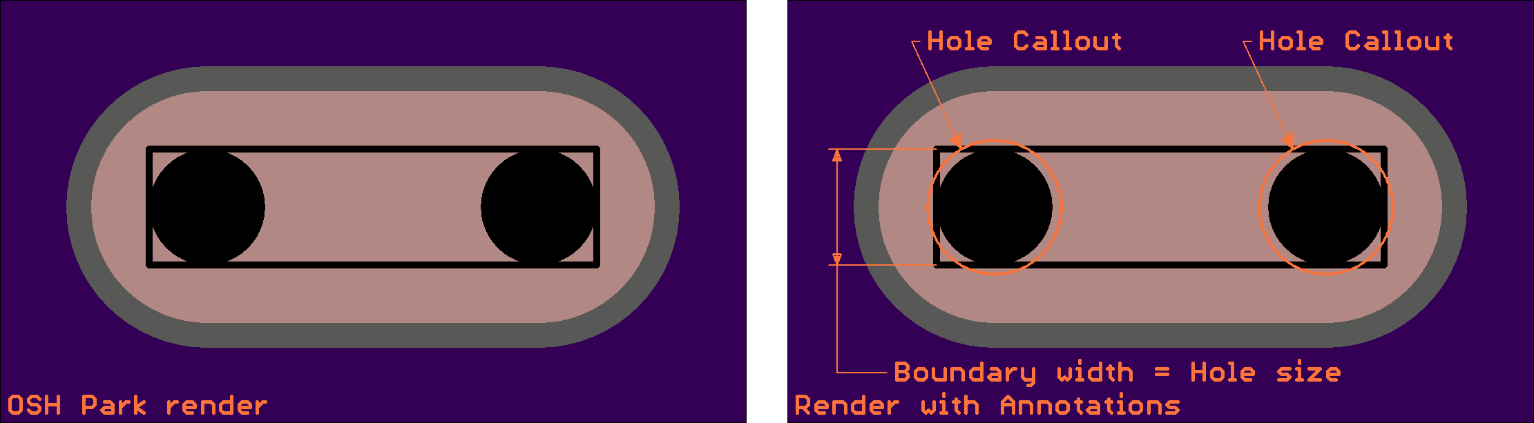
- Uses Slot Boundary callout with holes at each end
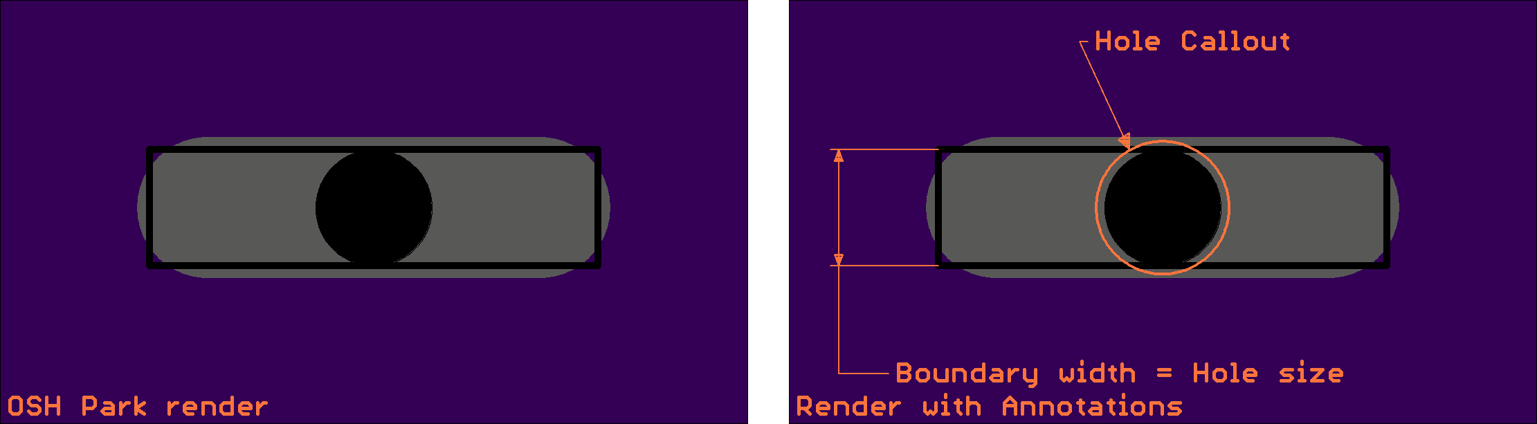
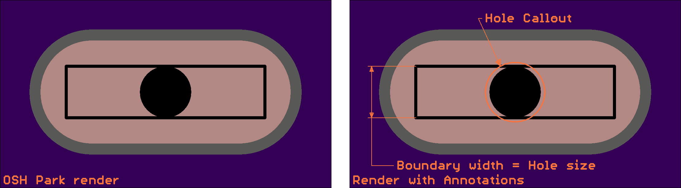
- Uses Slot Boundary callout with a single hole
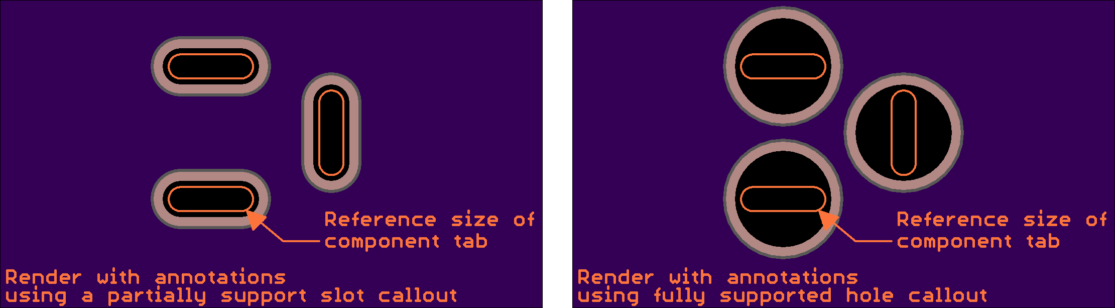
Previews of supported callouts
Partially Supported
We cannot guarantee these slot types. They typically work, but have known, non-zero failure rates of roughly 5-10%. This can occur on any board, even ones that were previously fabbed as intended. As a result, it is advised to minimize their use, and whenever possible use a suppported slot or a via instead. This is especially important on high-value boards, or time-critical orders. See below for tips on how to replace these features.
The following slot types fall into this category:
Small Non-Plated Slots
- No copper present below slot
- Has a width at between 0.04” and 0.1”
- Uses any non-plated hole callout
Plated Slots
- Copper present below slot and valid annular ring around slot.
- Have a width at least of 0.04”
- Uses any plated slot callout
Plated Slot Callouts
Plated slots can be indicated using any of the supported callouts.
Not Supported
Slots indicated with other specs or callouts are entirely non-supported, and will not be fabricated correctly. This includes, but is not limited to, slots listed below.
Slots with unsupported specs
- Slots width a width less than 40 mil
Slots with overlapping drill hits
We do not support drawing slots with overlapping drill hits. Overlapping drill hits will typically be removed, leaving a single drill hit for your slot. If they are fabricated, slots generated with this method are of very poor quality.
Note that due to rendering limitations, overlapping drills may appear as a slot on the previews. This does not mean the slot will be fabricated correctly, however.
Slots drawn with ambiguous instructions
While not easily detectable by our automated process, certain types of callouts can confuse the semi-automated process used for fabrication. Common examples of these are below, but other confusing drawings may also fall into this category.
- Slots drawn on a Board Outline layer that also includes significant junk data.
- Slots drawn across copper featurues such as pads or traces. These may be identified as junk data.
- Slot Paths drawn in a closed shape, such as large square cutouts. In these cases the drawing can be interpreted as a Slot Boundary for a cutout region instead, and will be the incorrect size.
Replacing Slots with Drills
When possible, in many cases slots can be avoided by simply using drill hits. Replacing the non-supported features with a slot will guarantee consistent and correct fabrication.