Common Errors with Board Outlines
The board outline layer provides a guide, which indicates to us where your board edge is located. This layer enables us to properly cut the board shape, as well as efficiently process your board.
A large number of errors can occur when generating this layer, and many design tools do not make the process simple. This is even more difficult if you cannot access the original design files, or are trying to order from a zip file someone else made.
If you’re not able to solve your issue with this guide, feel free to email us at [email protected], and we’ll do our best to help.
FAQ
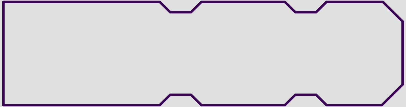
The layers look fine, but the board previews just show the outline.

This is typically due to the board outline not being fully connected.
Typically, this is the result of the outline being incomplete, as shown in the example. This may result in fabrication errors, and should be corrected.
Sometimes this is due to a thin outline having a minor error where it did not snap to the other line properly. While this typically will not cause fabrication errors, we recommend correcting it anyway.
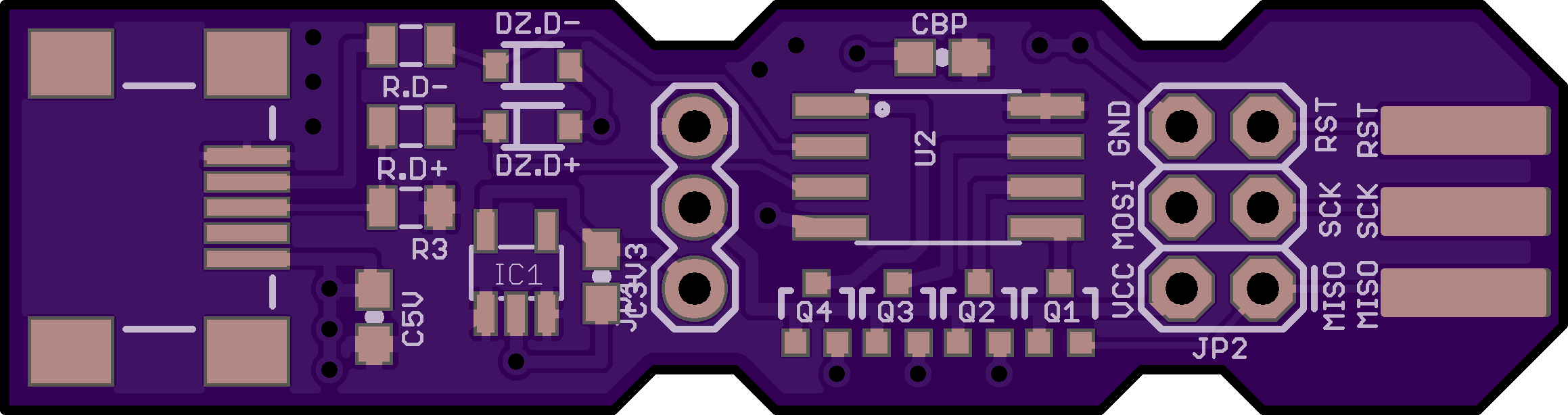
The layers look fine, but the board previews is solid black.
This is due to using a filled object to indicate the board shape, rather than using lines to indicate the board edge. Typically, these are made using Polygon, Rectangle, or Circle tools on a drawing layer. Less commonly, a tool generates a Board Area layer, as opposed to a Board Outline layer.
To correct this, simply define the board edge in your tool using lines and arcs instead of a filled object.

Why does it say “I can’t find a board outline”?
If the site also indicates Removed empty file <your outline filename>, then the outline was not correctly added to the outline gerber. Check out our Design Tool Help for how to generate this file correctly.
Otherwise, this is due to not being able to find the outline file at all. If you see the outline file, rename it so it has the .GKO extension.
If the file is not present, check our Design Tool Help for how to include the file in our CAM output.
If you’re still unable to generate an outline, you can Create A Board Outline using GerbV and the existing layers. This is sometimes necessary for older tools, or if you can’t access the original design file.
The size reported by the site is smaller than the actual size.
If your design is larger than this, it’s likely due to the board outline not containing the data we expect to see. Verify that your outline matches what we expect to see on a Board Outline File
Some tools, notably Altium, sometimes generates this error if we incorrectly select a Mechanical Pick And Place layer, usually on GM1 or GM2. Deleting all GM<number>, GKO files that do not contain the outline will correct this.
Eagle will sometimes generate this error when a design contains non-plated holes, but not an outline. Since the outline is not what we expect the rendering will be incorrect, and usually resemble the following.

The site says my board is too small to fabricate?
The smallest board we can fabricate is 0.25” by 0.25”. Designs smaller than this will generate a the warning Board must be larger than 0.25"x0.25.
If your board is larger than 0.25” by 0.25”, then this is a special case of the detected board being too small. See the above issue for detailed solutions.
Since we do not generate preview images in this case, you can only verify the outline using a gerber viewer such as Gerbv.

The site says my board is much larger than it actually is?
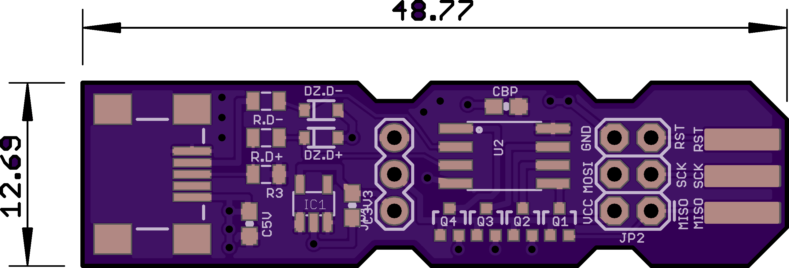
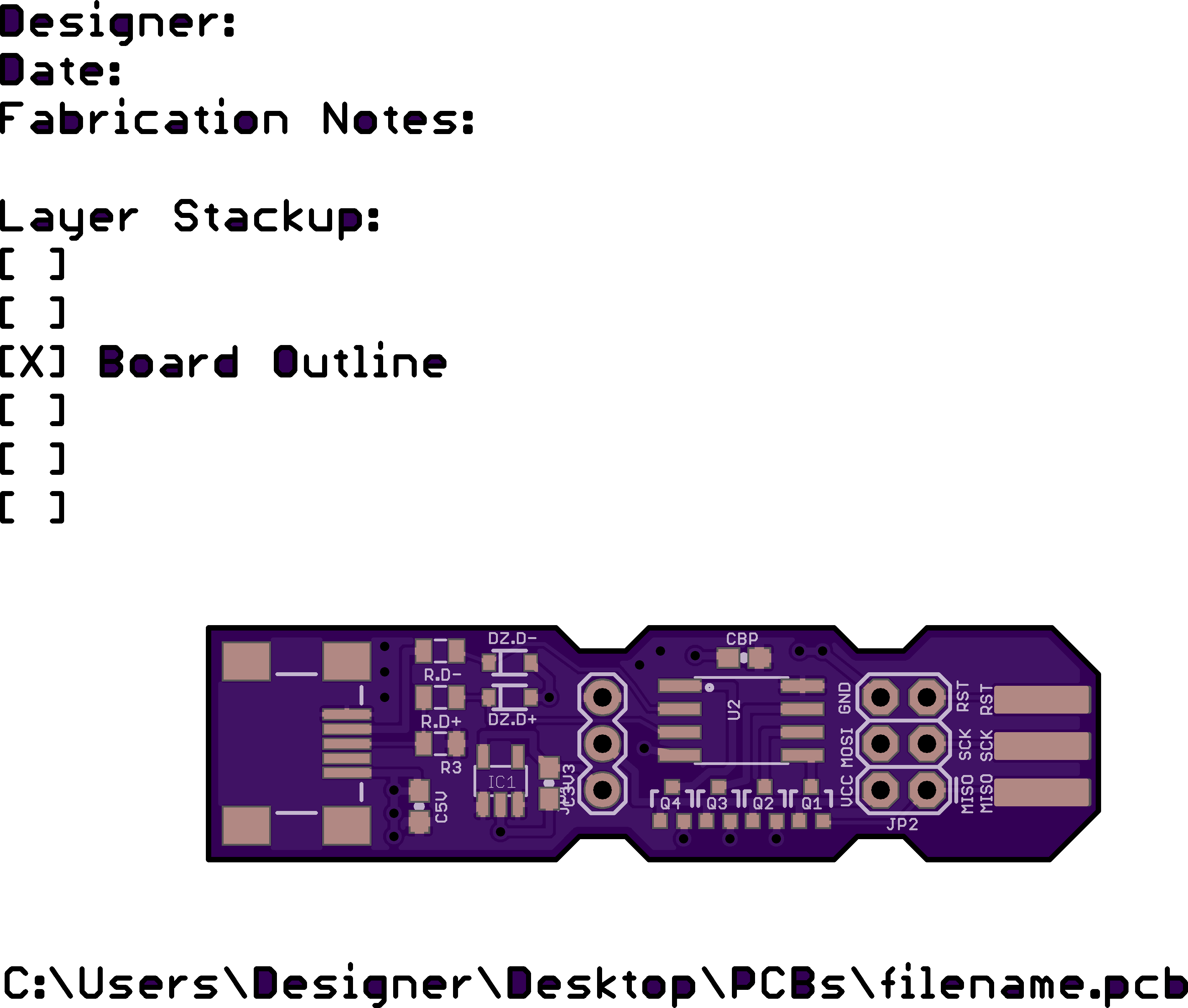
This is due to the site containing additional information on the outline. If that information is past the expected board edge, the board will be fabricated correctly, but will usually generate incorrect pricing.
The most common occurrences of this are for title blocks, measurements, and layer description text.
Some design tools will automatically add this type of data as part of the gerber output process. For most tools that do this, our Design Tool Help will contain instructions for how to disable it.
Deleting the additional information will correct this issue. If you do not have access to the original design files, you can use GerbV to edit the gerber files directly.